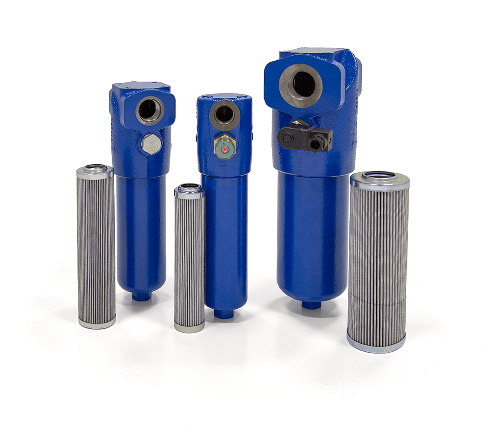
PFH High Pressure In-Line Filter Assemblies

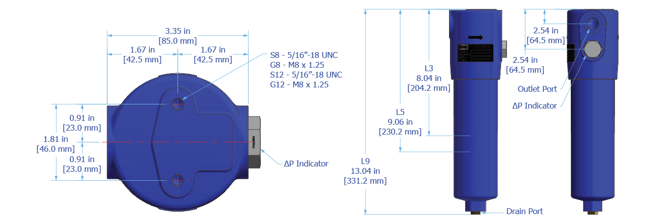
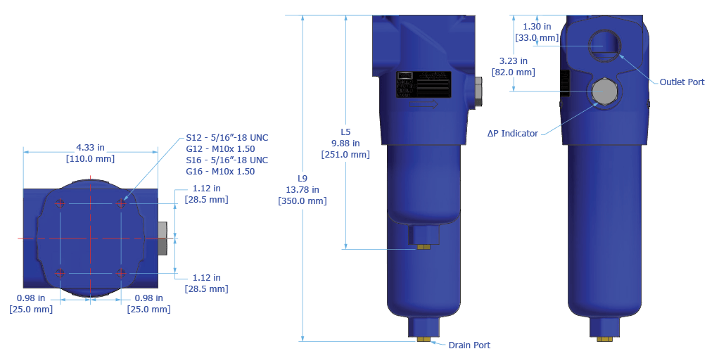
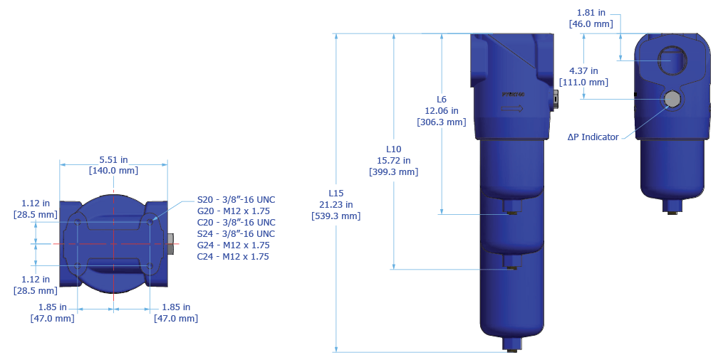
Hy-Pro’s PFH14, PFH55, and PFH167 pressure filters are designed to protect sensitive components in hydraulic circuits. Install the series upstream of specific components or directly after the pressure pump in smaller systems to minimize risk of failure and costly system downtime.

Ideal for use as a power unit pump discharge filter or a pilot filter, and to protect components that are sensitive to particulate contamination and require clean pressurized fluid for reliable operation, such as servo valves.

Max Operating Pressure: 6090 psi (420 bar)


Download Brochure

Operating Temperature

-20°F to 250°F

(-29°C to 121°C)

Operating Pressure

 PFH14

6090 psi (420 bar) max

 PFH55

6090 psi (420 bar) max

PFH167

6090 psi (420 bar) max

Flow Fatigue Rating

PFH14

2,000,000 cycles at 0-300 bar per NFPA T3.10.5.1, R2 2000

PFH55

2,000,000 cycles at 0-300 bar per NFPA T3.10.5.1, R2 2000

PFH167

2,000,000 cycles at 0-300 bar per NFPA T3.10.5.1, R2 2000

ΔP Indicator Trigger

73 psid (5 bard)

Element Collapse Rating

HP***N

450 psid (31.0 bard) max

HP***H

3000 psid (206.8 bard) max

integral Bypass Setting

PFH14

90 psid (6.2 bard)

PFH55

90 psid (6.2 bard)

PFH167

90 psid (6.2 bard)

MEDIA DESCRIPTION

M

G8 Dualglass, our latest generation of DFE rated, high performance glass media for all hydraulic & lubrication fluids. βx[C] ≥ 4000

A

G8 Dualglass high performance media combined with water removal scrim. βx[C] ≥ 4000

SF

Dynafuzz stainless steel fiber media βx[C] ≥ 4000

W

Stainless steel wire mesh media βx[C] ≥ 2

MATERIALS OF CONSTRUCTION

Head

Spheroidal “cast iron”

Bowl

Cold extruded steel

Exterior Coating

Powder coated

Fluid Compatibility

Biodegradable and mineral based fluids. For high water based or specified synthetics consult factory.

Replacement Elements
PFH Replacement Elements
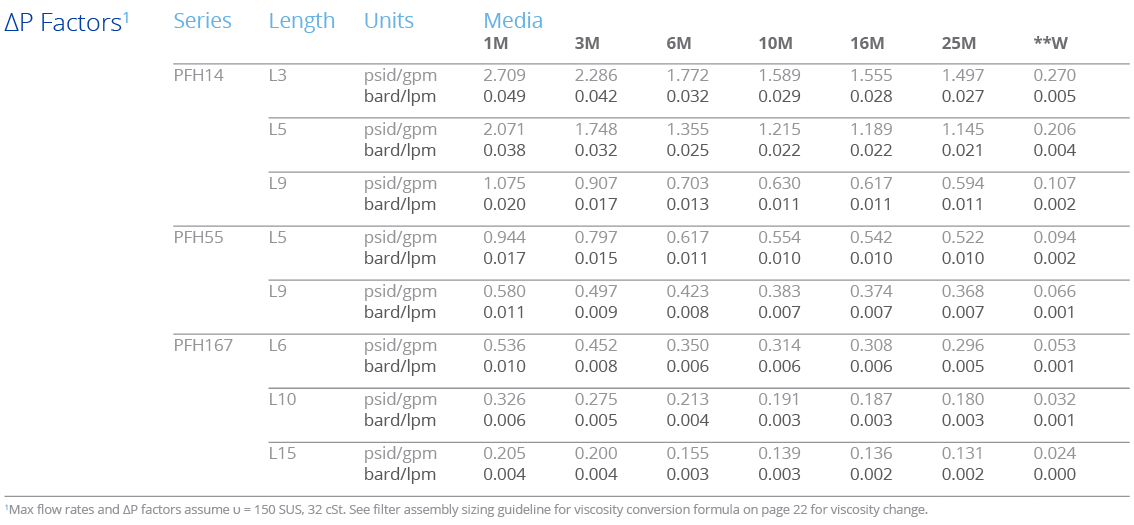
ΔP Factor
PFH ΔP Factors
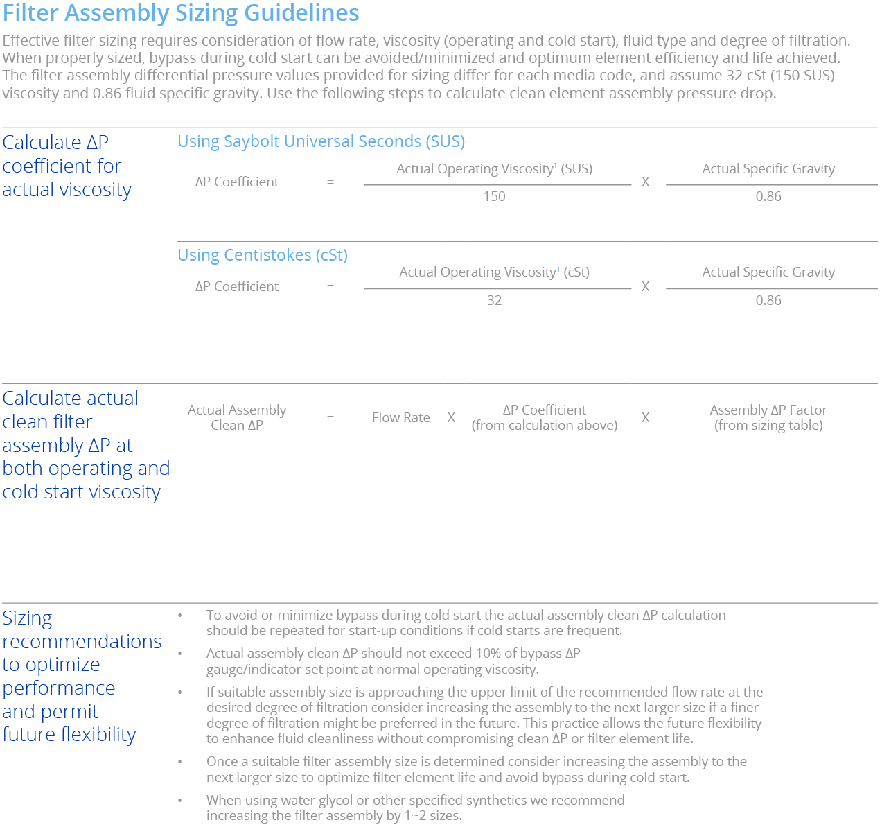
Max flow rates and ΔP factors assume υ = 150 SUS, 32 cSt. See filter assembly sizing guideline for viscosity conversion formula on page 22 for viscosity change.
Filter Sizing Chart
PFH filter sizing chart
Max flow rates and ΔP factors assume υ = 150 SUS, 32 cSt. See filter assembly sizing guideline for viscosity conversion formula on page 22 for viscosity change.