LFW Wall Mounted Filter Assemblies

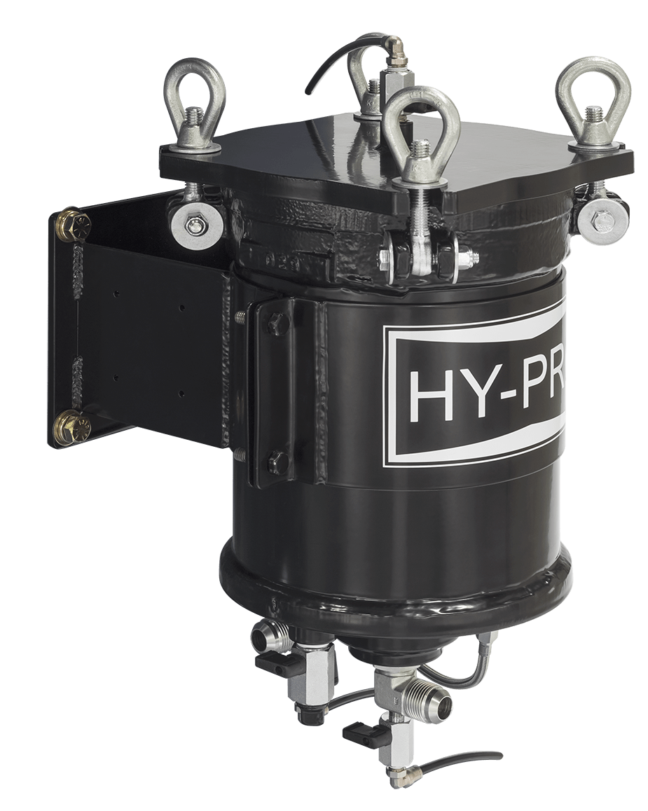
A compact, dedicated off-line contamination solution ideal for small reservoirs, gearboxes and diesel engine crankcase conditioning. Coming in at a whopping 0 ft2 of floor space, the LFW is designed to get your filtration off the ground and positioned conveniently for you, whether you’re polishing off that high viscosity gearbox oil or just want to add a little more protection for your critical components from heavy contaminants. And with Hy-Pro filter elements inside, the possibilities are endless for what you can do with the LFW.

Max Operating Pressure: 150 psi (10 bar)

Available options up to 250 psi (17.2 bar)


Download Brochure

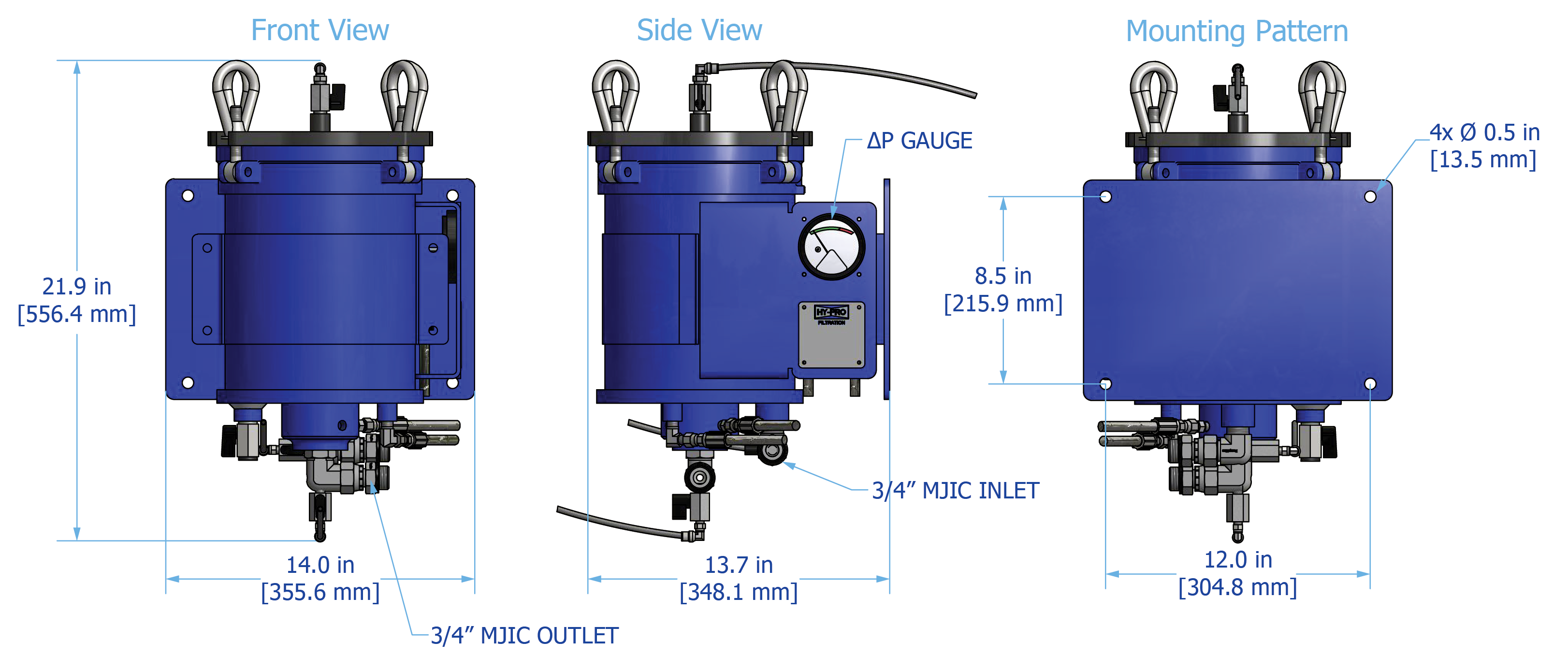
LFW Drawing
LFW Drawing

Operating Pressure

150 psi (10 bar) maximum standard. For 250 psi (17.2 bar) select Special option “X.”

Operating Temperature

Fluid Temperature

30°F to 225°F

(0°C to 105°C)

Ambient Temperature

-4°F to 140°F

(-20C to 60C)

Materials of Construction

Vessel

Carbon steel with industrial coating

Element Bypass Valve

Nickel plated steel

Media Description

M

G8 Dualglass, our latest generation of DFE rated, high performance glass media for all hydraulic & lubrication fluids. βx[C] ≥ 4000

A

G8 Dualglass high performance media combined with water removal scrim. βx[C] ≥ 4000

VTM

β3[C] ≥ 4000 particulate, insoluble oxidation by-product and water removal media

W

Stainless steel wire mesh media βx[C] ≥ 2 (βx ≥ 2)

Fluid Compatibility

Petroleum and mineral based fluids, #2 diesel fuels (standard). For specified synthetics contact factory for compatibility with fluorocarbon seal option. For phosphate ester (P9) or skydrol fluid (S9) compatibility select fluid compatibility from special options.

Replacement elements
LFW replacement elements
ΔP Factors
LFW ΔP factors
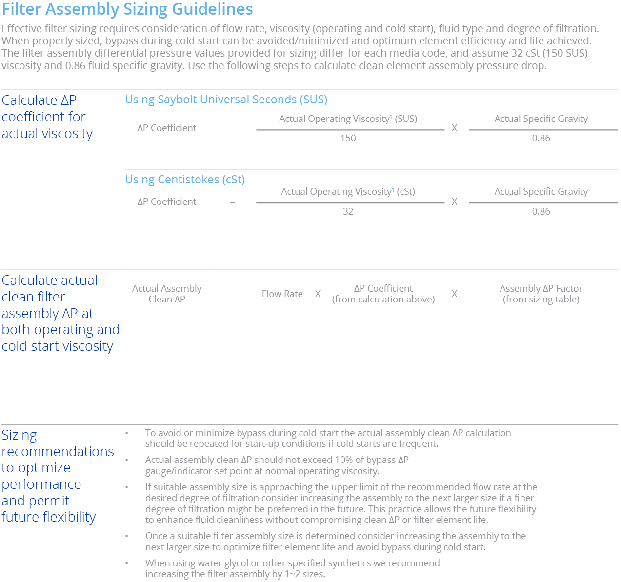
Max flow rates and ΔP factors assume υ = 150 SUS, 32 cSt. See filter assembly sizing guideline for viscosity conversion formula on page 22 for viscosity change
Filter Sizing Chart
LFW filter sizing chart
Max flow rates and ΔP factors assume υ = 150 SUS, 32 cSt. See filter assembly sizing guideline for viscosity conversion formula on page 22 for viscosity change